by Adrian Glasser
This is a blog about a computer controlled stretching instrument to be used in laboratory research for stretching soft and maleable lenses.
The natural, young lens is able to change its optical power to allow the young eye to focus at different distances. This is called accommodation and is mediated by a contraction of the ciliary muscle in the eye. However, with aging, the natural lens gradually becomes stiffer and after about 50 years of age, the natural lens has lost its ability to accommodate. In addition, with aging, the natural lens gradually becomes opacified. Intraocular lenses (IOLs) are used during cataract surgery to replace the natural lens in the eye to restore clear vision. However, most standard IOLs are not designed or intended to be able to change their optical power after they are surgically implanted in the eye. The ideal way to restore accommodation to the eye after cataract surgery would be to replace the cloudy natural lens with an artificial lens that is able to change power. Such accommodative intraocular lenses (A-IOLs) are being designed and tested.
Laboratory testing of accommodative IOLs can be challenging because there are no commercially available instruments for testing these lenses. Such testing would ideally include the ability to apply forces, to measure the magnitude of the applied forces and to measure the optical power of the lenses as the forces are applied.
Many accommodative intraocular lenses are designed so that they have maximum optical power without externally applied forces and so that the optical power decreases when they are stretched. Such A-IOLs can be tested with a lens stretching instrument that is also able to measure the optical power of the lenses and the magnitude of the applied stretching forces. This is a custom designed instrument to do just that.
This stretcher has eight 'arms' that can be attached to a sample (a lens or the tissues of an eye) to allow the sample to be stretched radially. Each arm is attached to a linear translation stepper motor. The mechanical parts of the stretcher were designed in CAD software to be 3D printed on a high-resolution 3D printer. The stepper motors are chosen for their size and linear range of travel suited to the particular stretching application and the 3D printed parts are designed and printed from materials of sufficient strength to withstand the forces required for the particular stretching application.
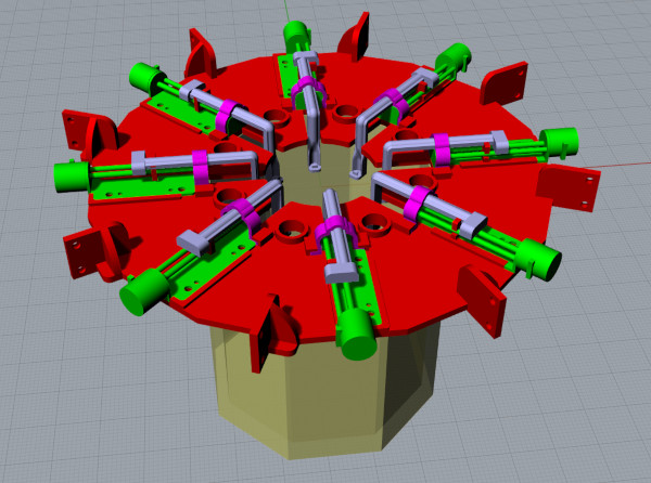
The stepper motors and the stretcher arms are mounted on the stretcher 'platform'. The platform rests on top of a clear, octagonal acrylic chamber. The chamber is transparent to allow for optical measurements of the lens during stretching. The chamber can be filled with saline to allow the stretching to be performed in a saline environment. The platform of the chamber is designed so that a thermometer and a water heater can be placed in the saline in the octagonal acrylic chamber to allow the saline to be maintained at a set temperature.
The software to control the stretcher is run on a laptop computer. The software communicates with a USB microcontroller and an electronic circuit (seen in the background of the video below). The software sends instructions to the microcontroller which in turn sends commands to stepper-motor driver boards to control the speed and movement of each stepper motor. These stepper-motors have a resolution of about 1.5 microns. The software application is simple demonstration software for rudimentary control of the stretcher and live video capture from the USB camera viewing the stretcher. The software allows for the motors to be run forward, backward or in cycles for a user-specified distance.
The video is best viewed by clicking on the full-screen icon at lower right on the video.
The video below shows the enhanced software application for controlling the stretcher and for controlling a scanning-laser system (not shown) to allow optical measurements of the lenses during stretching. The video demonstrates that each of the eight arms of the stretcher can be controlled independently. This would allow for stretching of lenses with only 4 attached arms, for example. Material samples can also be stretched linearly by using only two of the stretcher arms, for example.
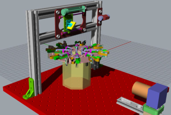
The stretcher is also integrated with a system for measuring the optical power of a lens and the changes in optical power of the lens with mechanical stretching. The optical measurement is performed with a scanning-laser system. The laser is directed to pass vertically downward after reflection off a front-surface mirror to pass through the lens as the lens is suspended in saline by the stretcher in the octagonal chamber. A video camera views the octagonal chamber and as the laser beam passes through the lens into the saline solution, the video camera captures the image of the laser beam in the solution and the path of the laser beam is identified automatically using image analysis. As the laser is scanned horizontally across the diameter of the lens, all the individual laser beams are digitized to reconstruct the laser ray-trace of the lens.
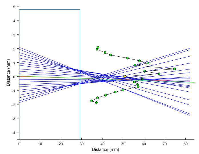
The image below shows a laser scan from a lens captured with the scanning laser system. The red beam is the beam that passes through the lens with the mimimum deviation and represents the optical axis. The green symbols are the location where each beam (blue lines) crosses the optical axis. The yellow symbol represents that average x and y position of all the green symbols and shows the lens focal length (about 50 mm in this case). The pattern formed by the green symbols represents the spherical aberration of the lens with the more peripheral rays intersecting the optical axis closer to the lens than the rays nearer the center of the lens. Laser scans such as this are performed while applying stretching to the lens to calculate the change in the lens focal length with stretching.
The stretcher and scanning laser are now both working well and reliably. Two slightly different versions have been built and deployed and are being actively used for slightly different applications.