
Adrian Glasser – Land of Iron volunteer
This blog describes the design, construction and use of a microcontroller operated photogrammetry turntable.
Tom, the Land of Iron Programme Manager asked me if I knew anything about photogrammetry turntables and if I could recommend one for him to buy. Well, I didn’t and I’d not had any prior experience with them, but I did a bit of online research and established that most of the cost-effective photogrammetry turntables were basically Lazy-Susans. For anyone who might not know, a Lazy-Susan is a circular tray on a rotating bearing that allows food (usually) to be accessed by rotating the tray. Cooking spices are often stored in a cupboard on Lazy-Susans so that the individual spice bottles can be found by rotating the Lazy-Susan. Photogrammetry is the process whereby many overlapping digital photos are taken of an object and the photos are then loaded into photogrammetry software that will generate a 3D model from the photos. Normally, the photographer will walk around the object taking photos of it. If light levels are low, a tripod must be used to keep the camera steady, but this quickly becomes tedious to pick-up, move and set down the tripod at numerous positions around the object. So, a Lazy-Susan could be used if the object being photographed is small enough to fit on the Lazy-Susan and the camera can then remain stationary on the tripod and the object being photographed is rotated by manually turning the Lazy-Susan. A turntable is also useful for photogrammetry because lights can be used to illuminate the object being photographed and the lights do not have to be moved as the object is rotated.
However, most of the photogrammetry turntables available must be rotated manually by hand. If one of these were used for photogrammetry, a photograph must be taken, the user must manually rotate the Lazy-Susan by some amount. After, rotating the Lazy-Susan, making sure it is stationary, the next photograph can then be taken. I immediately saw an opportunity for making a microcontroller controlled photogrammetry turntable that could automatically rotate the turntable by a fixed amount and then automatically trigger the camera to take the photographs. Such an automated photogrammetry turntable would dramatically increase the productivity of the photogrammetry process for objects small enough to fit on the turntable.
Camera Control
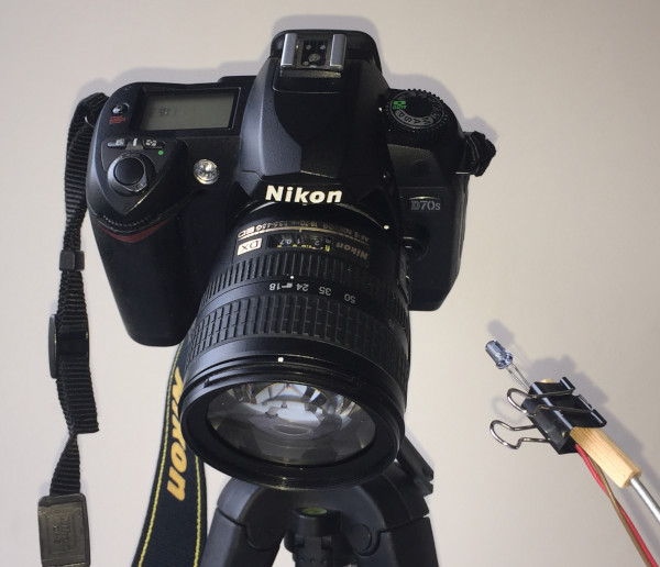
To use such an automated photogrammetry turntable requires having a camera that can be triggered with a ‘remote’. Many digital cameras have a wired remote that can be plugged into the camera with a push-button on it. Some digital cameras have infrared (IR) remotes and an IR detector on the camera to trigger the camera to take a photograph. The IR remote sends a specific, timed sequence of flashes via an IR light-emitting diode (LED) to the camera and the camera recognizes this specific sequence of IR flashes to trigger the camera to take the photograph. Simply using a TV remote and pointing it at the camera and pushing the button on the TV remote won’t trigger the camera (unless, by chance, one of the buttons on the remote happens to send the exact, required IR signal to the camera). The camera that Tom has, happened to have an IR detector on it, so I chose to use an IR LED to trigger the camera. The camera also allows a wired remote to be used, but to use that with the photogrammetry turntable would require either taking the push-button apart or cutting and rewiring the cable. Further, it would have required using an electrical signal sent to the camera and this has the potential, if not done correctly, to damage the camera. So, using the IR signal from an IR LED is the more desirable and far safer option.
The Plan
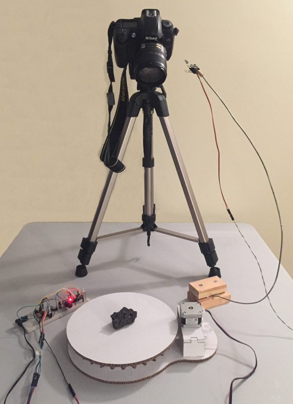
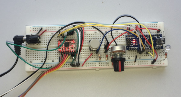
So, I planned to make an automated photogrammetry turntable. It would be controlled by a programmable microcontroller (an Arduino Nano). The turntable would have a stepper motor with gears to rotate it. The controller electronics would have a push-button to start it and it would have an IR LED to trigger the camera. Pressing the push-button would rotate the turntable through 360 degrees in a fixed number of steps. At each step the turntable would rotate through the required angle, then it would pause a short time, it would trigger the camera to take a photograph by flashing the IR LED, then it would pause again for a short time to ensure the camera exposure was complete and then it would rotate the turntable again, etc. The sequence would then end once the turntable had been rotated through 360 degrees. I chose to have this done in 20 steps, so 20 photographs would be taken of the object as it was rotated through 360 degrees. For the microcontroller, I chose to use an Arduino Nano because of it’s small size so that it could easily be used with an electronics prototyping bread-board. To run the stepper motor required a stepper-motor driver board be used in the circuit.
Triggering the Camera
It was first necessary to establish what sequence of IR flashes was needed for the IR LED to trigger the camera. The sequences needed by some cameras can be found online with careful internet searches. These are usually posted by individuals who have figured out the sequence needed for their own cameras and who have posted this information online. Tom happened to have a Nikon D750 camera. I also happened to have an older model Nikon camera that also had an IR detector on it and I had the Nikon IR remote for the camera. So some serendipity helped. I was able to build a simple electronic circuit with an IR detector connected to the microcontroller and programmed the microcontroller, connected to my laptop, to time the flashes from the IR remote and to display the timing sequence on my laptop screen. By recording this sequence of flash durations and time intervals, I could then reprogram the microcontroller to deliver this same sequence from an IR LED. I was hoping that Tom’s Nikon D750 used the same signal used by my older camera. After testing this IR sequence on my camera and making sure it worked reliably, I tried it on Tom’s camera. At first it did not work, but my Nikon IR remote did work on his camera, so with some more careful analysis of the sequence, I modified the sequence slightly in my software and then it worked fine. It turns out that Tom’s camera must have had tighter constraints on the IR sequence required to trigger it compared to my camera.
Stepper Motor Driver
The next step was to get the microcontroller to drive the stepper motor. After some online research, I chose to use a A4988 stepper motor driver board and a NEMA-17, 200 steps per revolution stepper motor. The A4988 stepper driver allows for micro-stepping, which means that the stepper motor can be made to turn in smaller steps, so this allows driving the turntable more smoothly. The driver can be switched to micro-steps as small as one-sixteenth of a step. This means that a 200 steps per revolution stepper motor can be used with 16 x 200 = 3200 steps per revolution. This driver board also allows more direct software control of the motor movement rather than using a less-transparent Arduino stepper library. This driver also allows the current to the motor be adjusted with an on-board potentiometer. While these are more technical considerations, they do ultimately make life easier in the long run. With some playing around, I got the microcontroller to drive the stepper motor and to do this with micro-steps. This allows very small angular rotations of the stepper motor.
Turntable Design
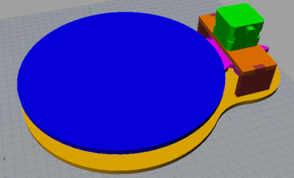
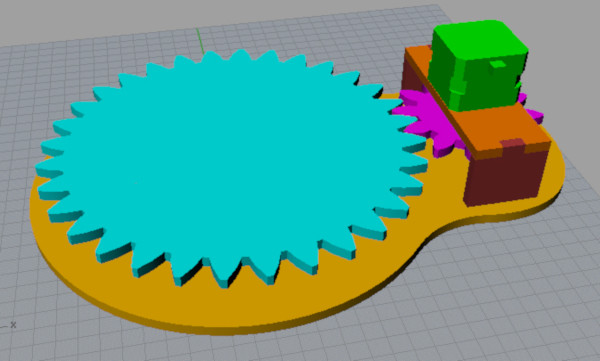
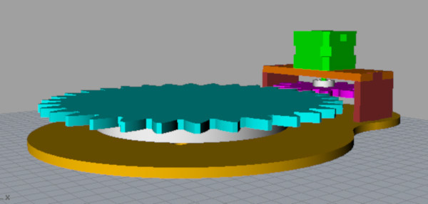
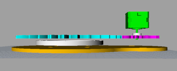
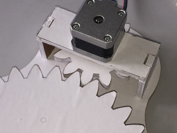
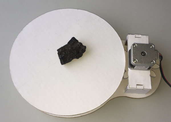
The next step was to design the turntable in Computer Aided Design (CAD) software. I initially thought I’d make a crude prototype using 6 mm thick cardboard from a box I had lying around and then once that was working, have the parts laser-cut or CNC milled from plywood. I didn’t want the weight of the objects being photographed to rest directly on shaft of the stepper motor because this might stall the motor, and also because the motor has a small shaft, if the objects were not centered perfectly above the motor shaft, I thought this might cause a tilt or might break the turntable. So, I decided to make the turntable using two gears with the smaller gear attached to the motor that would drive the larger gear that would rest on a Lazy-Susan bearing. Having a smaller gear drive a larger gear also improves the gear ratio as more stepper motor steps would then be required to turn the larger gear through 360 degrees. Further, with the larger gear resting on a Lazy-Susan bearing it would mean that this larger gear could take more weight. As it turns out, the prototype cardboard turntable works perfectly well, so I've not yet made a new turntable from plywood.
Calculating the Gears
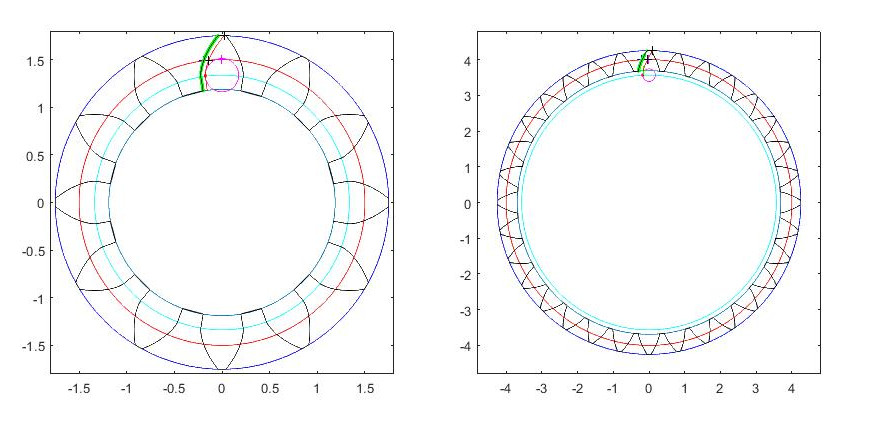
The shape of the gears was calculated using a Matlab software program. Gears, it turns out, are highly engineered mathematically based components. Of course, simple gears can be made easily, will work and can be found in many places, including toys and laser-cut or CNC milled plywood objects. However, correctly designed gears work well together and are designed to work more efficiently and move heavier objects. The individual teeth for gears are calculated to allow the teeth to contact each other at the right places and the right angles as the gears rotate. The larger gear was chosen to have an 8 inch pitch diameter with 32 teeth and the smaller gear to have a 3 inch pitch diameter with 12 teeth. The calculations ensure that the teeth from gears with different numbers of teeth engage correctly. The Matlab software saved the (x, y) coordinate points for the gears and the file with these points can be loaded into the CAD software. Once loaded, the points are then connected with lines to create the outline of the gears. The outline can then be extruded into 3D gears. The gear ratio chosen resulted in 8640 stepper motor steps per revolution of the turntable.
Turntable Assembly
After putting the initial layout together in the CAD software, the hardware needed was identified, including machine screws, bolts, a stepper motor, a motor bracket to mount the smaller gear to the motor shaft, a Lazy-Susan bearing, etc. Once those parts were ordered and arrived, they were measured carefully with calipers and added to the CAD design, including where the screw holes were, the screw hole diameters, the screws, etc., so that all the individual parts fitted together correctly in the CAD layout. The individual parts where laid out in a flat plane in the CAD software and the layout was printed on paper. The printed pages were glued to a sheet of cardboard and the individual parts of the turntable were cut out of the cardboard with a fine jig-saw. The cardboard cut-outs and the hardware was all assembled. The IR LED is positioned on the end of a long piece of fence-wire which is stiff enough to hold the LED, but soft enough to bend easily to position the LED so that it points towards the camera IR detector.
Turntable Electronics
The electronics circuit entailed putting together the microcontroller, the pushbutton, the stepper motor driver and the IR LED on an electronics bread-board. A white light LED was added that also illuminates when the IR LED sends the signal to trigger the camera. Sufficiently long wires were needed for the IR LED to enable it to be mounted close enough to the camera and for the stepper motor so that the turntable could be run with the circuit positioned out of the camera field of view. Since the turntable is started by pressing the push-button, a cancel function was also added to the push-button such that if the push-button was pressed again after the turntable sequence had started, the turntable cancelled the sequence and returned to its start position. This allows the sequence to be aborted if something is found to be wrong after starting the sequence.
Programming the Microcontroller
The Arduino Nano software was written using the Arduino Integrated Development Environment (IDE). Despite the complicated sounding name, this is a very simple, free application that can be downloaded from Arduino. It runs on a computer with the microcontroller and associated electronics circuit connected to the computer with a USB cable. Once the code is written, it is uploaded to the Arduino and the Arduino can initially run tethered to the computer via the USB cable to test the code. This facilitates an easy, rapid iterative testing process. When running the microcontroller tethered to a computer, the microcontroller can be programmed to send information, comments and number back to the computer to be displayed on the screen so it is easy to debug a program and to get it working. Of course, once everything is working, the microcontroller can be unplugged from the computer and can run untethered from the computer provided that the microcontroller has a power supply. As described above, the microcontroller was programmed to start the photogrammetry sequence with the press of a push-button. That would trigger a photograph via the signal sent to the camera from the IR LED. After a short pause to ensure the camera exposure is completed, the turntable turns 1/20 of 360 degrees = 18 degrees, it pauses a second or two to allow the turntable to stop moving, then it triggers the camera again. Once started, if the push-button is pressed again, this resets the turntable to exit the sequence and returns the turntable to the start position. Because the photogrammetry turntable might be used in different light conditions requiring a longer or shorter camera exposure, a potentiometer was added to the circuit which when adjusted changes the pause time after each exposure to allow for longer or shorter exposures.
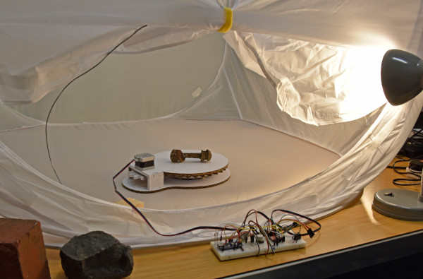
Below is a short video of the photogrammetry turntable in action. Towards the end of the video the push-button is pressed a second time to cancel the sequence, to reset the turntable, and to return it to its start position.
Powering the Turntable
Although a microcontroller can be run from a battery, the power needed to run a stepper motor dictates that the circuit for this photogrammetry turntable needs to be powered from a AC/DC adaptor. I used a 9V, 1A power supply and this provides ample power to drive the stepper motor.
Other Possible Designs
A photogrammetry turntable like this could also be designed for use with a smart-phone camera mounted on a tripod. Smart-phone cameras can be triggered remotely either with a wired cable or with a Bluetooth selfie remote. The wired cable could be attached directly to a microcontroller or the Bluetooth remote could be hacked and the push-button for the remote wired up to a microcontroller to trigger the camera remotely via Bluetooth. This is not difficult to do and it works well. The result could be a photogrammetry turntable for use with a smart-phone camera. Most smart-phones these days have sufficiently high resolution cameras that would work perfectly well for photogrammetry.
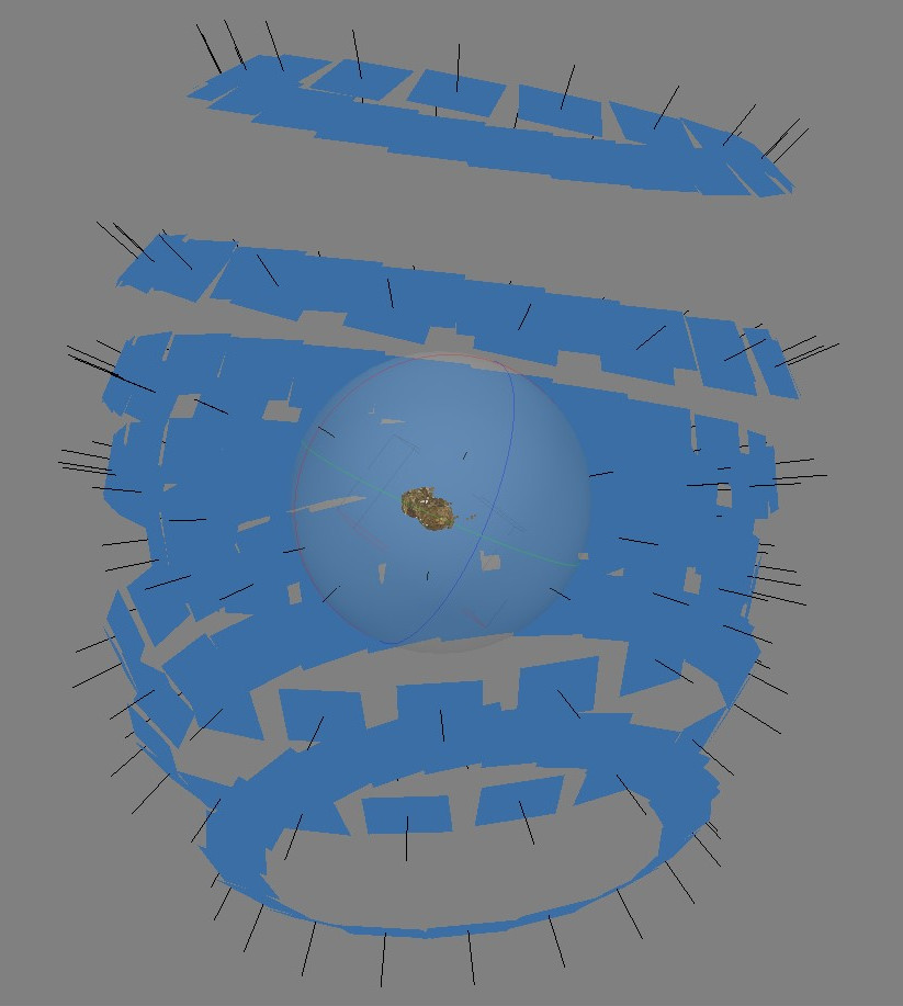
A 3D photogrammetry model can be made free of any background by first photographing one side of the object and then turning the object upside down and repeating the sequence of photographs on the other side, now facing up. If sufficient overlap is achieved in the photographs, the photogrammetry software will recognize that some of the photographs are from the underside of the object and will orient the images correctly to create a complete model that can be viewed from any orientation. The end result is that images can appear to have been taken from all around the object. As can be seen below in the reconstruction image from the photogrammetry software, there is an apparent tilt to the axes from which the photographs were taken because the camera was just moved vertically on the tripod for the different 360 degree turntable rotations. For the model of this rusty bolt, 169 photographs in total were taken.
Here below is the Sketchfab 3D model constructed using the photogrammetry turntable from the Land of Iron Sketchfab page. The quality of the model is dependent on the quality of the photographs taken, their resolution, the focus, the aperture used and how that affects the depth of focus of the images, the lighting used, and how cleanly the background can be distinguished from the object. For an object that has some length to it, it is not desirable to try to get photographs that contain the entire object because the limited depth of focus of the camera will mean that all parts of the object are not in sharp focus at the same time and this will degrade the quality of the final model.