Adrian Glasser
This blog is about inexpensive USB video cameras with electronically controlled infrared cut-off filters.
Video cameras have come a long way since when I first encountered them. Today, it is possible to buy inexpensive USB video cameras with some nice features. These are essentially webcams, but they can be used for many applications.
Any video camera has an image sensor (or detector) on which the image is projected from the camera lens. The sensor usually has a fairly wide spectral sensitivity, meaning it is sensitive to a wide range of wavelengths of light. This includes sensitivity into the infrared wavelengths of light (beyond the red end of the visual spectrum). These are wavelengths of light that human eyes are not sensitive to. Infrared light (IR) is used in many applications. Since humans are not sensitive to it, it can be used to illuminate scenes that appear to humans to be in complete darkness. Security cameras and surveillance cameras are probably the most common example of this. Many such cameras have a bank of IR light emitting diodes (LEDs) around them to illuminate the scene for the IR-sensitive camera.
It used to be common when ordering video cameras to have to specifically order them either with or without an IR-cut-off filter in them. This is a piece of glass that is usually located directly over the image sensor and glued down around the image sensor so the cut-off filter cannot easily be removed. The IR cut-off filter blocks IR light from reaching the sensor, but allows the visible wavelength of light to reach the sensor. By blocking the IR light, this ensures that the sensor only responds to the visible wavelengths and this helps to produce an image that has the right colours in it. When a camera is used without an IR cut-off filter over the sensor, the image has a washed-out appearance because of the presence of IR illumination in the environment (including from indoor lighting or from the sun).
It is often useful to use IR light and to block out the visible light. This can be done by buying a video camera without an IR cut-off filter over the sensor (or by breaking and removing the IR cut-off filter - don't try this unless you really know what you are doing because it can irreversibly damage the image sensor). If using IR light, it is also useful to put a visible light cut-off filter right in front of the image sensor to block off any visible light. Such visible light cut-off filters can be bought or a piece of exposed and developed film can be used for this - if this can be found anywhere anymore. The blackened film blocks visible light, but allows infrared light to pass through it. Most cut-off filters that can be purchased specify what wavelength of light are blocked and which wavelengths will pass through.
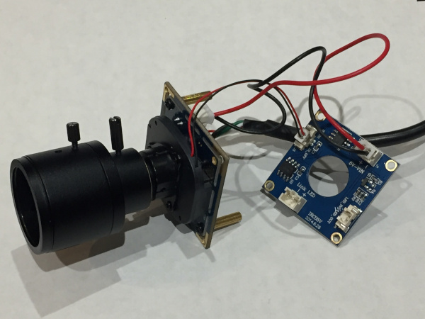
It is now possible to buy very inexpensive USB video cameras that also have electronically controlled IR cut-off filters. The cut-off filter resides between the lens and the image sensor in a little plastic housing with a black and red wire going to it. Video cameras with these electronically controllable IR cut-off filters usually also have an electronic circuit to control the IR cut-off filter and they are often sold with an array of IR LEDs mounted around the camera lens. The array of LEDs includes a light sensor (a photocell) and the circuit on the camera will detect the ambient illumination and if it is below a pre-set threshold, the IR LEDs will be turned on and the IR cut-off filter will be moved off the image sensor. These video cameras will have good colour correction in daylight and will also have good infrared sensitivity at night.
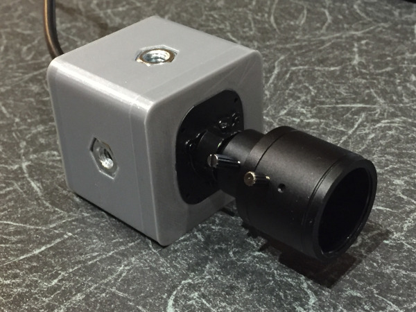
I recently bought such a video camera and have played around with it a little. It is a board camera or a so-called camera module - meaning that it is sold without a housing. This might be a problem for some, but a benefit for others. Since it is so easy to design and 3D print virtually anything these days, it is straight-forward to 3D print a perfectly acceptable housing for the camera so that the camera can be mounted in a manner suitable for any specific application.
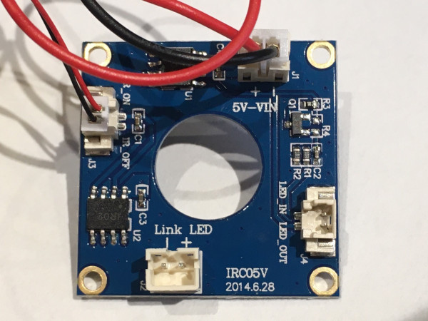
By applying or removing +2V to LED_IN pin on the J4 connector on the IR cut-off filter control circuit (see image above), it is possible to electronically control whether the filter is in front of the image sensor or if it is moved away from the path of the image sensor. I have done this (see video below) with a microcontroller which is also controlling the illumination of two LEDs. The microcontroller turns on and off two LEDs simultaneously every 2 seconds. The LED on the left is a visible white light LED and the LED on the right is an IR LED. Both LEDs go on and off at exactly the same time. In addition, the signal to the LEDs is also sent to the IR cut-off filter to move the IR cut-off filter out of the path of the image sensor when the LEDs are turned on. The movement of the IR cut-off filter is a little slower than the illumination of the LEDs, so both LEDs come on and then about 500 milliseconds later the filter is moved. This turns out to be useful because it allows the effect of removing the filter to be seen very clearly. When the IR cut-off filter is in front of the image sensor, the IR LED (on the right) appears to not be on (it also cannot be seen with the naked eye) but when the IR cut-off filter is moved away from the image sensor, it is clear that the IR LED is in fact on. After the two LEDs are turned off, the IR filter moves back in front of the image sensor after about 500 milliseconds and this can be seen by the colour change in the video image.
Although there is some latency to the movement of the IR filter, this is such a nice little feature of these video cameras (that I had to write a blog about it). The cameras generally cost less than a modest meal (the cost of the camera depends on the lens on the camera), but the ability to electronically control the IR cut-off filter offers so many possibilities. Of course, as already mentioned, it allows good colour correction in visible light as well as good IR sensitivity. The camera could be used in applications where it might be desirable to capture one image with visible illumination and another image of the same scene with IR illumination. This could all be controlled by external electronic circuits with sensors to detect light levels or with sensors to detect movements or other external events.
With a custom designed, 3D printed enclosure with embedded tripod mounting bolts on all 4 surfaces, this camera is now ready for use in a variety of projects. With the ability to electronically control the switching of the IR filter this offers a host of possibilities for both visible and infrared light applications.